Getting Started
Several “project files” have been included in the GSEIM distribution. In this section, we will see how to execute (run) some of these projects and view the simulation results.
First, let us see where the project files are located. As explained in the Installation Instructions, there are two ways to run GSEIM in linux:
- installing pre-built image: In this case, the project files are
not available locally, and the user should therefore download the GSEIM
.zipfile and unzip it in a suitable directory. - building from source: In this case, the project files are already available locally.
In either case, the user should be able to locate the directory
/gseim-master.
We will denote the absolute path for this directory by $GSEIM_MASTER.
Note that $GSEIM_MASTER would vary from user to user, depending
on where the GSEIM zip file has been copied/unzipped.
The project files are located in
$GSEIM_MASTER/gseim_grc/src/gseim/test_data/input/. We will denote
the absolute path to this directory by $PROJ_DIR.
Free acceleration of induction motor
File menu \(\rightarrow\) Open \(\rightarrow\) Select the project file
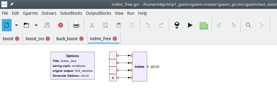
$PROJ_DIR/machines/indmc_free.grcas shown below.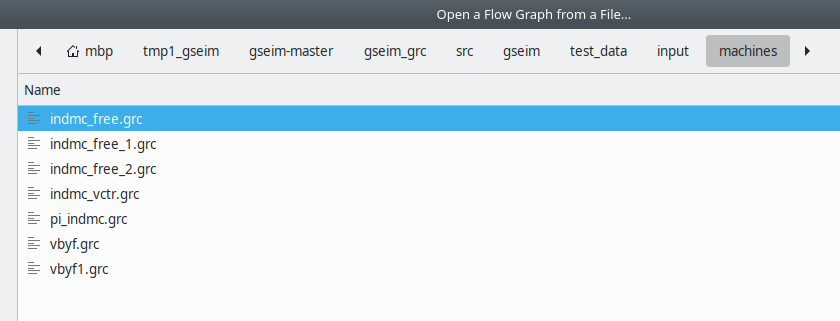
The project schematic diagram will appear as shown below.
Click on
Generate circuit file. This would create the circuit file$PROJ_DIR/machines/indmc_free.inwhich is used by the GSEIM solver for solving the set of ODEs associated with the project schematic. Notice that a separate window opens to show the progress of this step. If the flow graph generation is successful, Program Completed will appear at the bottom of that window. Close the window.Note that the circuit file (which has extension
.in) always gets created in the same directory as the project file (which has extension.grc).Click on
Run simulation. This invokes the solver which runs the simulation and creates the data files as specified for this project. Again, a separate window opens to show the progress made by the solver. The data files are also created in the same directory as the.grcfile which in this case is$PROJ_DIR/machines/.Click on
View results. The plotting GUI would show up as a separate application, as shown below.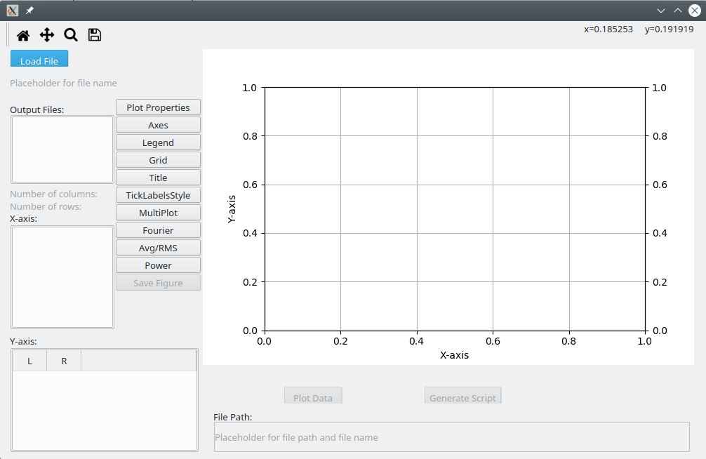
Click on
Load File, and select the circuit file$PROJ_DIR/machines/indmc_free.in. The data file created by GSEIM for this particular project will appear as shown below. Names of the variables stored in the data file are listed. Selecttimeas the x-axis andwrm(the angular speed of the motor) as the y-axis to obtain the plot shown below.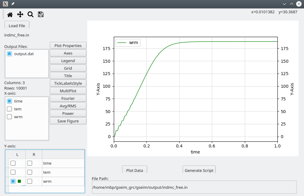
Neutral point clamped inverter
File menu \(\rightarrow\) Open \(\rightarrow\) Select the project file
$PROJ_DIR/dc_to_ac/npc_inverter.grc. The project schematic diagram will appear as shown below.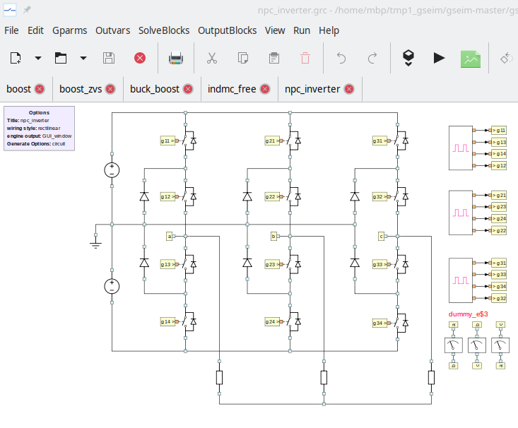
Click on
Generate circuit file. After the Program Completed message appears, close the window, and click onRun simulation. Close the window when the program is completed.Click on
View results. In the plotting GUI, click onLoad File, and select the circuit file$PROJ_DIR/dc_to_ac/npc_inverter.in. Selecttimeas the x-axis andiaas the y-axis to obtain the plot shown below.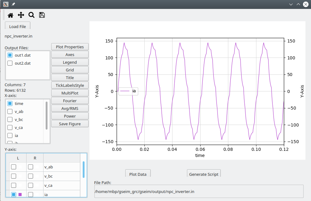
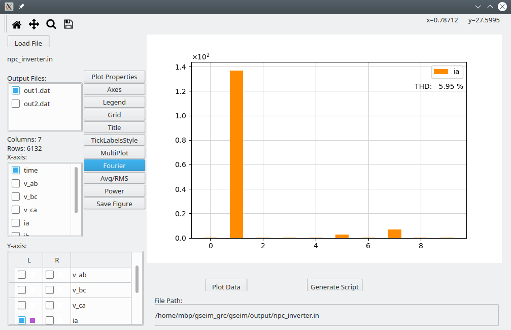
We can view the Fourier components of the signal
iaby clicking onFourierin the plotting GUI and entering values fortStartandtEnd, as shown below. Note that the difference betweentStartandtEndis expected to be one period of the signal being analysed.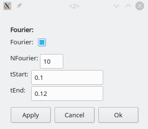
The Fourier components for
iawill be displayed by the GUI.